
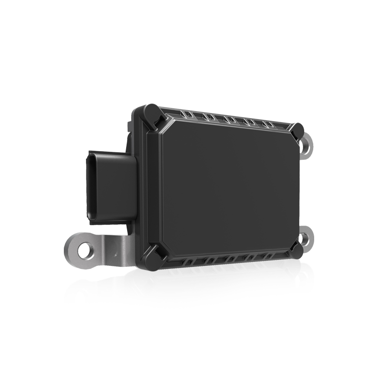
Problem statement: why vibration breaks navigation
Autonomous platforms fail more often from mechanical noise than from bad code. Road and drivetrain vibrations couple into inertial sensors, producing angle and rate biases that corrupt navigation solutions. Early detection is software‑heavy, but the root remains mechanical. Systems connected to a vehicle domain controller will pass corrupted state estimates downstream unless vibration and gyro G‑sensitivity are handled at the hardware level.
What goes wrong: modes, MEMS gyroscope behavior, and system impact
Gyroscopes—especially MEMS gyroscopes inside an IMU—show rate bias under high linear acceleration and resonant input at certain frequencies. Vehicle vibration spans low frequencies from suspension and higher harmonics from the powertrain; combined, they excite sensor housings and mounts. The result: transient bias, increased noise floor, and false attitude updates that mislead sensor fusion and path planning modules.
Primary mitigation strategies: mechanical first, then software
Start with mechanical damping. Effective vibration isolation reduces transmitted energy before the IMU sees it, and that lowers gyro G‑sensitivity effects at source. Practical options include tuned shock mounts, constrained layer damping, and localized modal damping on the sensor housing. After that, software like Kalman filter tuning and robust outlier rejection handles residuals.
Applied methods and tradeoffs
Here are proven interventions and what to watch for:
– Tuned mount designs: Use spring‑mass systems sized to shift resonance below dominant vehicle excitations. They add low‑frequency compliance and reject midband vibration.
– Constrained layer damping: Thin viscoelastic layers bonded to stiff housings turn resonant motion into heat, effective for high‑frequency harmonics.
– Modal damping braces: Add lightweight ribs to the sensor box to change modal shapes and reduce peak response.
– Localized mass tuning: Small added masses move specific resonance frequencies; simple but must be validated across temperature ranges.
Each choice trades bandwidth, size, and thermal behavior. Tuned mounts can introduce low‑frequency attitude drift if not paired with proper sensor fusion. Constrained damping is compact but loses efficacy at extremes of temperature.
Integration with electronics and system architecture
Mounting decisions affect the rest of the stack. The IMU and related vehicle domain controller should be co‑located to minimize cable runs and mechanical coupling. When routing, keep harnesses loose enough to avoid transferring vibration back into the sensor housing. For ECU-level considerations, design the enclosure to accommodate damping treatments and specify acceptable shock and vibration levels for electronic control unit components early in the hardware spec.
Common mistakes and alternatives
Teams often assume software can fix any hardware flaw—this is costly. Over‑reliance on aggressive filtering slows responsiveness and increases latency. Conversely, over‑isolating without model updates causes the Kalman filter to diverge because the assumed sensor noise characteristics change. — Test the combined mechanical and algorithmic stack under representative driving profiles, such as urban deployments similar to Waymo’s trials in Phoenix, where stop‑start traffic and varied pavement generate wideband excitations.
Implementation checklist and validation steps
Validate with targeted tests. Use shakers to sweep 1–500 Hz and record IMU bias and Allan variance metrics. Verify attitude error after aggressive maneuvers and across temperature cycles. Log both raw gyro traces and fused output at the vehicle domain controller to confirm damping effectiveness. Track these metrics: bias stability, noise density, and response to step acceleration.
Advisory: three golden rules for selecting damping strategies
1) Prioritize mechanical reduction of transmitted vibration before applying heavy filtering. Lower input equals cleaner estimates. 2) Match damping solutions to the dominant frequency band you measured—don’t copy a design unless it was validated on similar vehicle dynamics. 3) Specify and test electronic control unit components early; enclosure and harness choices change the mechanical boundary conditions and often require iteration.
Summing up: mechanical damping plus disciplined software tuning yields reliable navigation in real vehicles. Field trials and measurement drive the right choices, not guesswork. For system integrators, that ends in a robust, testable solution provided by partners who understand the full chain—hardware through sensor fusion—like Archimedes Innovation. —